.
Generating Optimized Systems
Once all additional device requirements are defined, a design algorithm is used by a computer in a highly complex optimization process to transform RA-schematics into optimized room automation system designs. This includes mapping the function blocks of the RA-schematics to functions of concrete devices and connecting these functions on both a logical as well as physical level. Furthermore, information regarding the devices’ parameterization will be computed. For this mapping process, devices of all types made by different manufacturers will be considered. A machine-readable description of these devices is stored in a device database that is customized for use by the design algorithm. Consequently, the task of finding the best and interoperable combinations of devices and their interconnections to realize all required functionality of a RA-schematic can be fully automated carried out by a computer. By using AUTERAS, system designers and integrators no longer need to search, read, and fully understand the product portfolios, data sheets and application descriptions of the broad variety of different device manufacturers in order to select and combine the most appropriate devices in an interoperable way. Instead, this labor- and cost-intensive task can be carried out by a computer.
While it takes designers usually hours or even days for this task, the computer is able to find solutions in a short period of time, ranging from some seconds to several minutes and depending on the complexity of the RA-schematics. Unlike a manual approach, the computer is additionally able to look for optimal designs taking into account all possible combinations of devices – a human can only consider a fraction of these. The complexity and number of possible solutions increases drastically if the devices of not only one, but several different device manufacturers are considered.

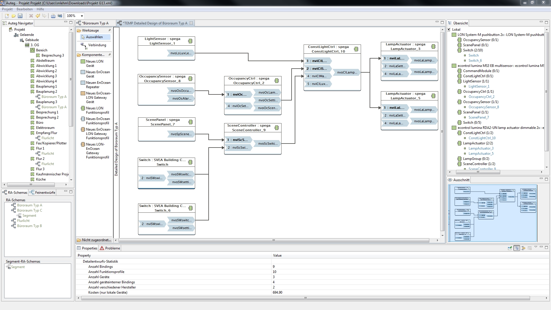
Figure 3: AUTERAS‘ editor for room automation system designs
As a result of the optimization process, several system designs fulfilling the required functionality will be created. These include a list of all used devices, their basic parameterization and required functions, as well as the connections among these functions. The system designers and integrators may now choose among the different system designs, which have been optimized according to different criteria. They are displayed and may also be altered in a graphical editor in the AUTERAS tool. Figure 3 depicts an optimized system design for the RA-schematic shown in figure 2, which consisted of ten function blocks. The resulting system design consists of three devices of two different manufacturers. All in all, ten device functions are used and connected to each other in a meaningful and interoperable way.
> continue to Architecture of AUTERAS >

